Solutions
Compact Transmission Solutions for Grid Expansion and Uprating
Bottlenecks in greenfield builds & retrofits
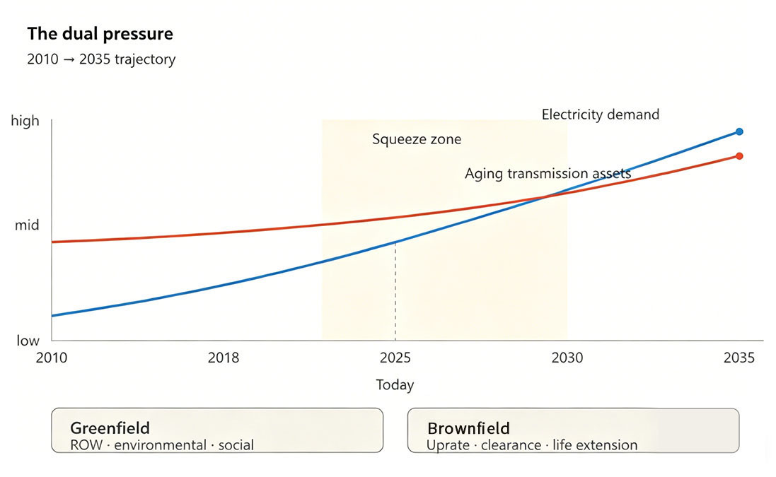
The global grid is under pressure from both ends
Electrical · structural · environmental limits trace to materials
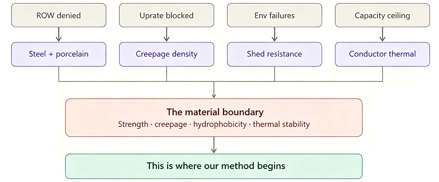
Strip every bottleneck down to its root, and you reach the same answer: it isn't an engineering problem. It's a materials problem.
Field deployments quantified outcomes · client evidence
Real validation does not happen in the lab. It happens on the grid
The global grid is under pressure from both ends
On one side, the build-out: rising load, renewable interconnection, and accelerating electrification demand more transmission lines, faster. On the other side, the rebuild: more than half of the world's transmission assets are over 30 years old and need voltage uprating, current uprating, or ground-clearance restoration.
Whether greenfield or retrofit, projects keep stalling at the same chokepoints — right-of-way denials, community opposition, tower geometry that won't accept higher voltage, insufficient insulation clearances, and reliability collapse under extreme environments.
This isn't a single country's problem, or a single project's. It is the structural bottleneck the entire global grid is now passing through.
Where projects stall
Three constraint families across global transmission projects
- Insulation distance insufficient
- Pollution & lightning withstand
- Current capacity limited
- EMF ground influence
- Tower reuse space limited
- Cross-arm length & swing
- Load margin insufficient
- Sag & ground clearance
- ROW acquisition & relocation
- Ice, strong wind, galloping
- High altitude & salt fog
- Wildfire & vegetation distance
trace to materials
Strip every bottleneck down to its root, and you reach the same answer: it isn't an engineering problem. It's a materials problem.
Right-of-way denied? Because the tower must be more compact, and at some point the steel cross-arm and porcelain string run out of geometry — which is set by the strength-to-weight ratio of steel and the volume of porcelain.
Voltage uprate blocked? Because the required insulation distance grows, but the existing tower geometry can't — which is set by the creepage distance porcelain can deliver per unit length.
Reliability collapse in extreme environments? Because pollution resistance, ice shedding, and UV stability are not enough — which is set by the intrinsic chemistry and physics of the material itself.
Peel every constraint to its last layer, and the answer is the same: the ceiling of any product is the ceiling of its material.
To break the engineering bottleneck, we must first break the material boundary. That is where our methodology begins.
Our method begins at the material innovation.
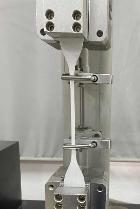
1. Silicone Rubber — Materials & Formulations for >50 Years Service Life
| Technical Specification Items | EMAGE | DL/T 376 | IEC/TR 62039 |
|---|---|---|---|
| Shore Hardness ShA | 65±5 | ≥50 | — |
| Tensile Strength (MPa) | ≥4.0 | ≥4.0 | — |
| Tear Strength (kN/m) | ≥12.0 | ≥10.0 | ≥6.0 |
| Elongation at Break (%) | ≥300 | ≥150 | - |
| Volume Resistivity (Ω·cm) | ≥1.0×10¹² | ≥1.0×10¹² | ≥1.0×10¹⁰ |
| Dielectric Strength AC (kV/mm) | ≥22.0 | ≥20.0 | ≥20.0 |
| Dielectric Strength DC (kV/mm) | ≥30.0 | ≥30.0 | - |
| Tracking Resistance and Electrical ErosionResistance |
≥1A4.5 | ≥1A4.5 | ≥1A3.5 |
| Hydrophobicity | HC1–HC2 | HC1–HC2 | HC1–HC2 |
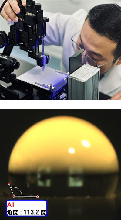
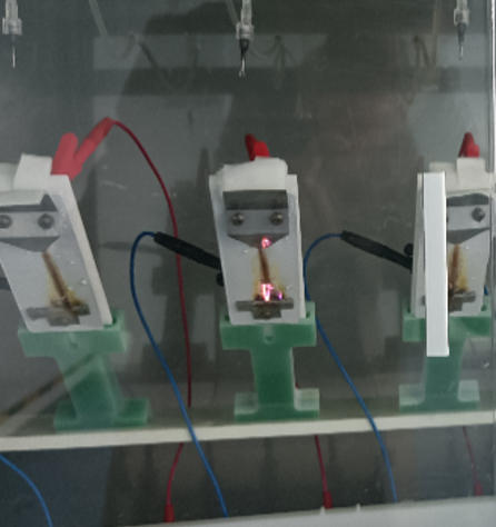
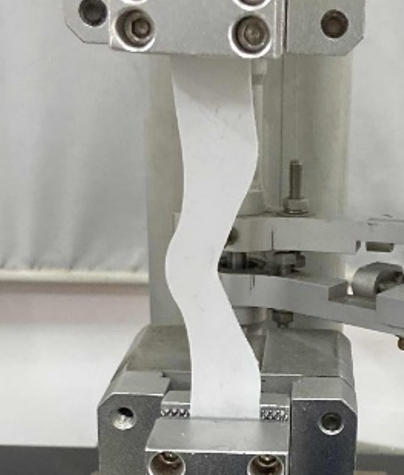
Accelerated Aging Study
Aging primarily includes factors such as UV radiation, temperature, acid rain, humidity, and sand erosion. Currently, accelerated aging tests under corresponding operating conditions and the establishment of aging life evaluation models have been completed.
| Types of Aging | Reference Standard | Test Duration | Test Conditions | Life Prediction Model |
|---|---|---|---|---|
| Thermal Oxidation Aging | ISO 11346 | 5000 h | 100°C, 120°C, 150°C (High temperature exposure) | Arrhenius Model |
| UV Aging | ISO 4892-3 | 5000 h |
Irradiance: 0.76 W/m² Cycle: 8 h UV + 4 h Condensation |
Equivalent Accumulation Model |
| Hygrothermal Aging | IEC 62217 | 5000 h | 50 ± 2°C, 93% RH | Hallberg-Peck Model |
| Acid Aging | Acid Effect | 1224 h | 25°C, 40°C, 60°C, pH = 2.3 (Acid solution) | Equivalent Accumulation Model |
| Sand Abrasion Aging | IEC 60721-2-5 | 24 h |
Spray speed: 50 m/s Sand concentration: 3 g/m² |
Equivalent Accumulation Model |
2. FRP Rod & Hollow Extruded Tube
Innovative material formulation: E-CR reinforced fiberglass + high-strength epoxy resin + additives
| Key Indicators | EMAGE Hollow Pultruded Tube |
|---|---|
| Water Absorption Rate | <0.05% |
| Dye Penetration | >15 min |
| Tensile Strength | ≥400 MPa |
| Axial Bending Strength | ≥450 MPa |
| Axial Compression Strength | ≥520 MPa |
| Breakdown Voltage | ≥30 kV/mm |
| Glass Transition Temperature (Tg) | ≥105°C |
| Key Indicators | EMAGE Core Rod | Standard Requirements |
|---|---|---|
| Water Absorption Rate | <0.05% | <0.05% |
| Dye Penetration | >20 min | >15 min |
| Tensile Strength | ≥1200 MPa | ≥1100 MPa |
| Bending Strength | ≥900 MPa | ≥900 MPa |
| Water Diffusion Current | <50 μA | <50 μA |
| Volume Resistivity | ≥10¹¹ Ω·m | ≥10¹⁰ Ω·m |
| Breakdown Voltage | ≥30 kV/mm | ≥30 kV/mm |
| Glass Transition Temperature (Tg) | ≥120°C | ≥110°C |
Material is the foundation. Product is its expression.
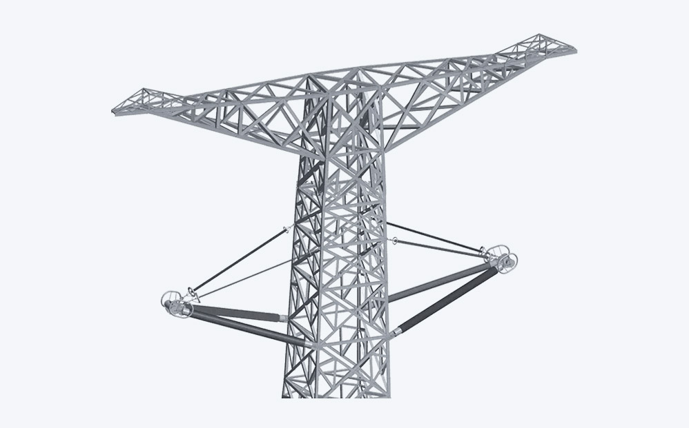
CICA
CICA is a key component used in composite conductors for overhead power transmission. It integrates a high-strength composite core with insulating and reinforcing materials to provide excellent mechanical strength, durability, and electrical performance. CICA helps improve conductor reliability and supports higher transmission capacity.
EXPLORE MORE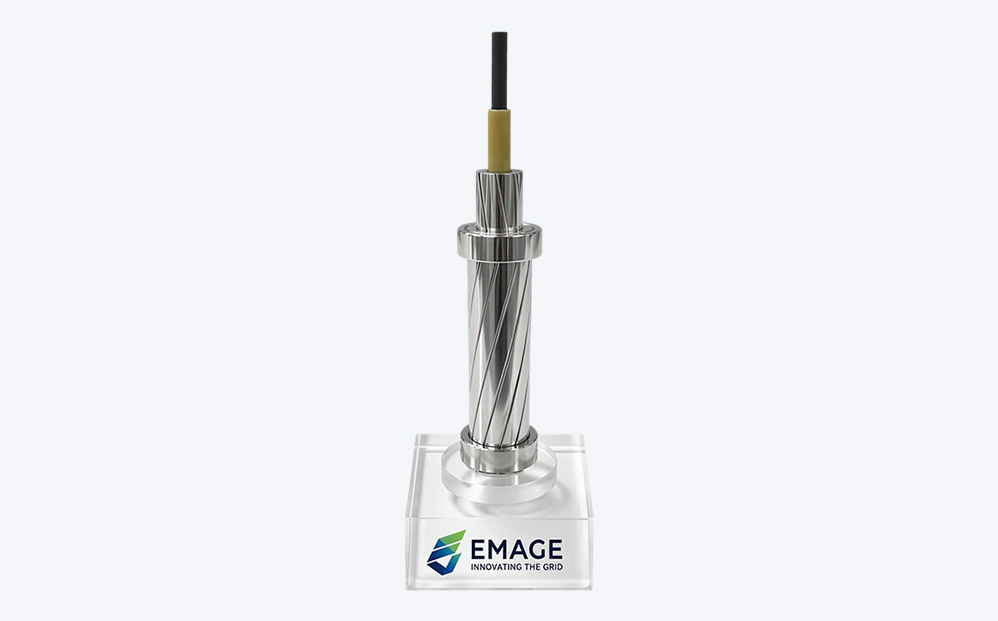
ACFS™ Conductor
ACFS™ conductor is a high-performance overhead power line conductor that replaces the traditional steel core with a new designed carbon fiber–reinforced composite core. This advanced design improves strength, efficiency, thermal performance, and cost efficiency.
EXPLORE MOREBefore any EMAGE technology is deployed in the power grid, it undergoes end-to-end validation from simulation to physical testing — ensuring that innovation is engineered for true grid-grade reliability.
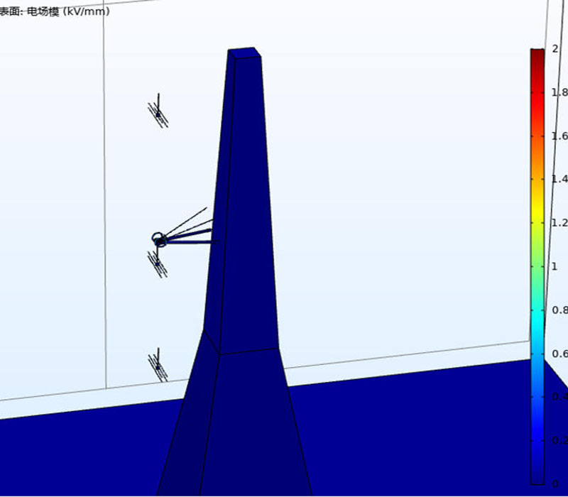
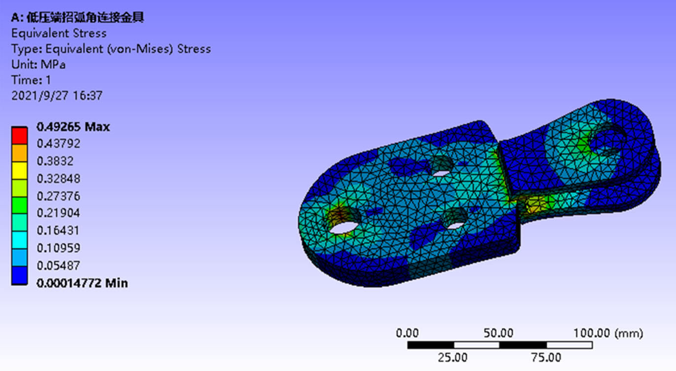
CICA Electrical and Mechanical Simulation
| Parts | Industry Requirements (kV/mm) | EMAGE Standard (kV/mm) |
|---|---|---|
| Shed kV/mm | 0.42 | <0.42 |
| Fittings kV/mm | 1.8 | <1.8 |
| Triple-point kV/mm | 0.35 | <0.35 |
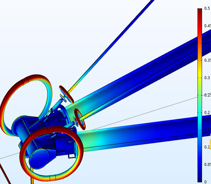
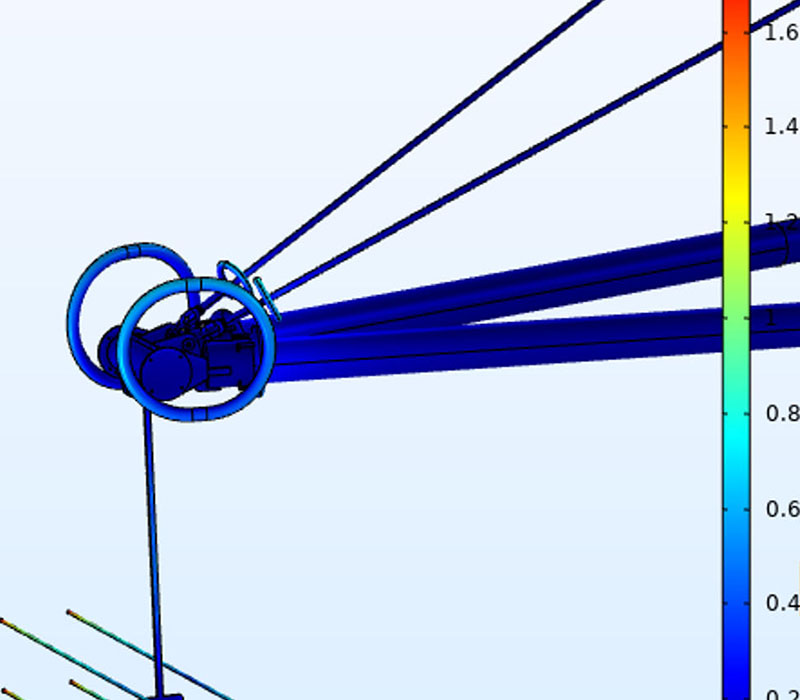
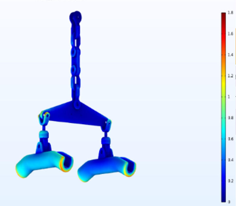
Overall mechanical simulation
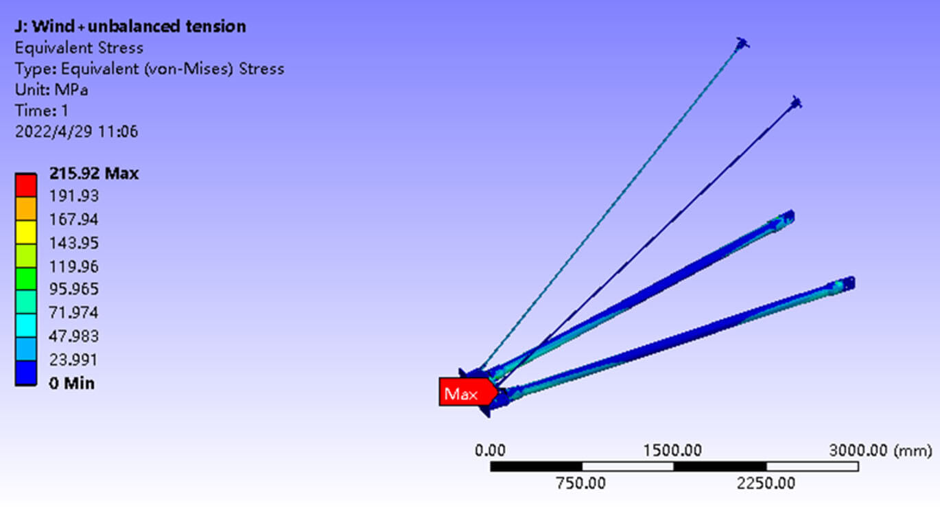
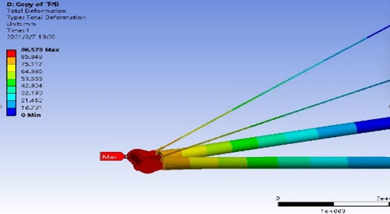
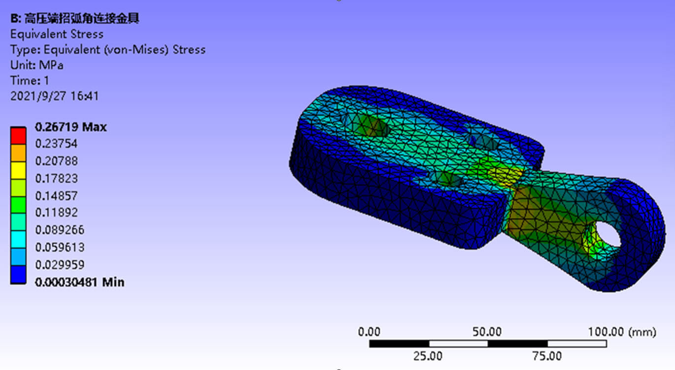
CICA Electrical and Mechanical Tests
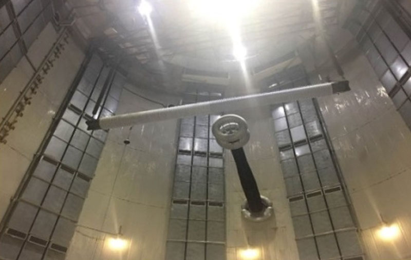
Artificial Pollution test
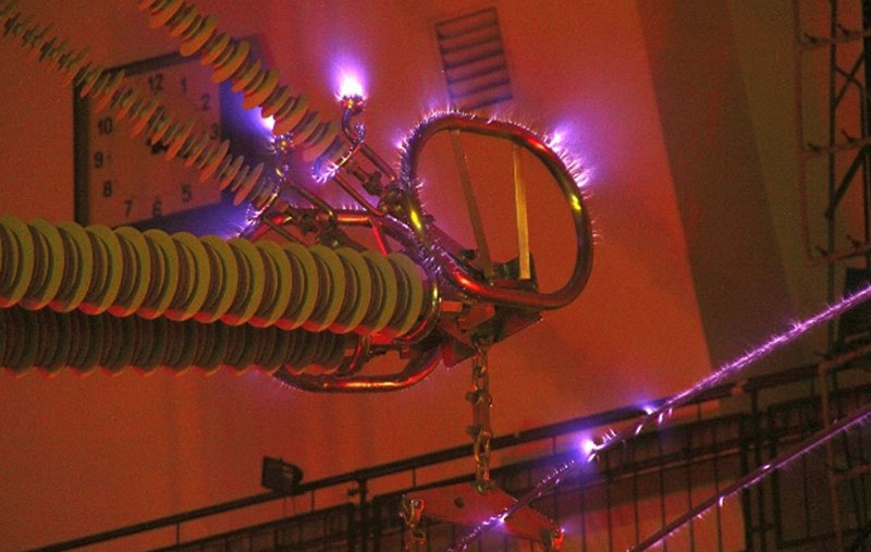
RIV test
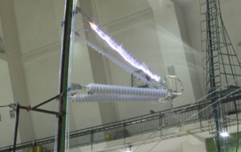
CIFO test
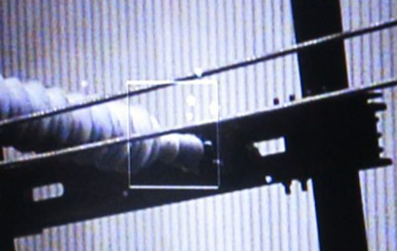
Visual corona test
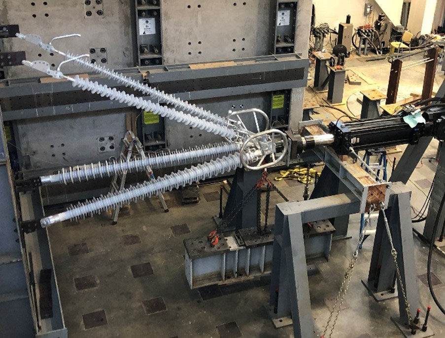
Assembly mechanical test
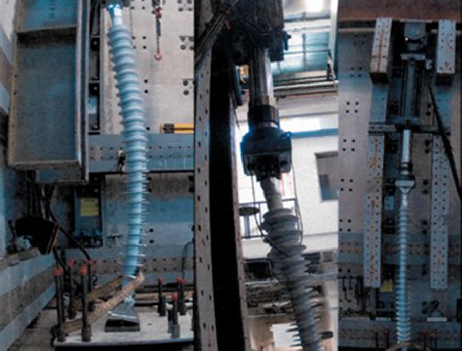
Fatigue test
Solution Innovation: CICA + ACFS
No single product rebuilds a grid
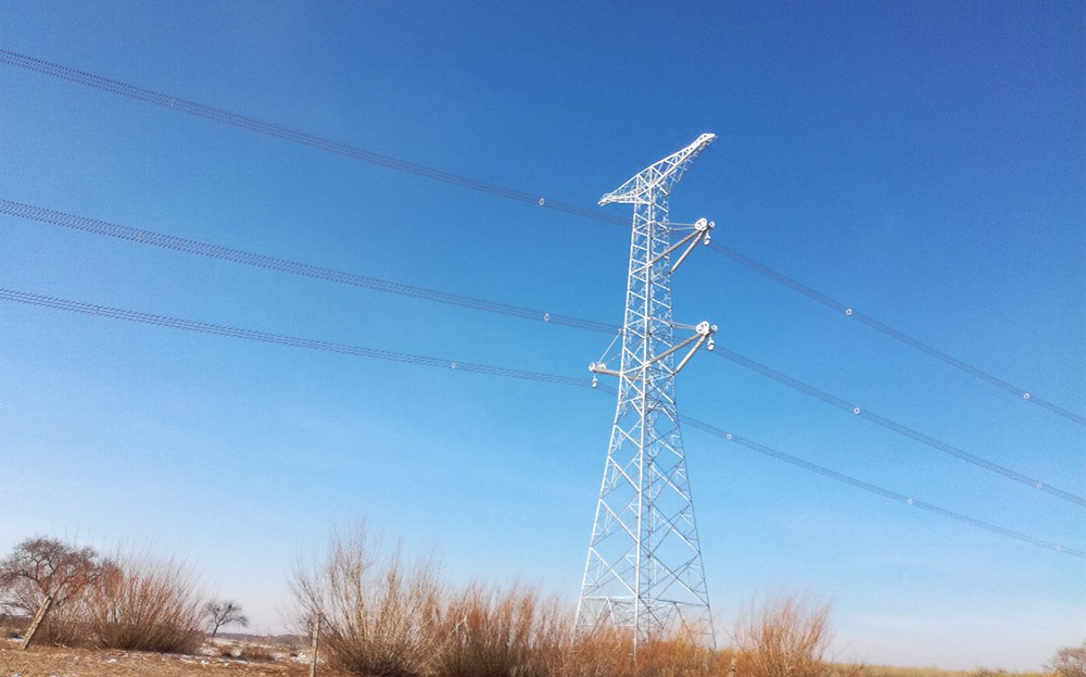
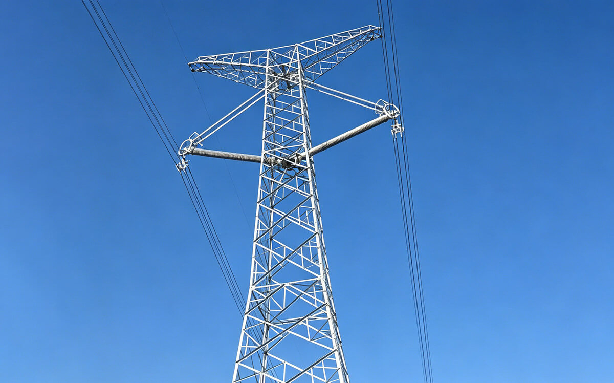
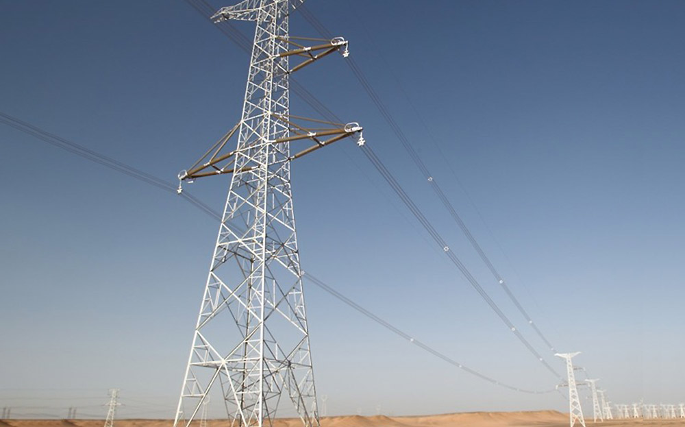
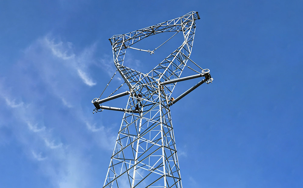
The real breakthrough comes from redesigning CICA and conductor as a single integrated system — the CICA defines tower-head geometry and insulation coordination, the conductor defines current capacity and sag behavior, and only when both are co-optimized do right-of-way width, tower height, current capacity, and per-km cost improve simultaneously.
Greenfield Solution
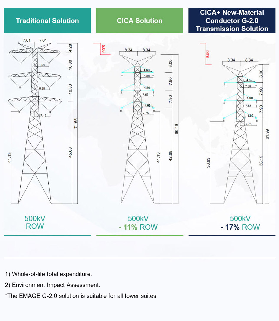
Compared with traditional solutions, the EMAGE solution enables project-specific optimization of:
- Materials
- Size
- Performance
- Spans
- Easement width
- Line length
- Environmental clearing
- Carbon emissions
- Visual amenity
- Heritage outcomes
CAPACITY can DOUBLE while unit capacity cost drops significantly
IMPROVED through life SAFETY and MAINTENANCE performance
Reduced ENVIRONMENTAL impact (and offset requirements)
FASTER EIA2 and permitting, shortening grid build-out
Reduced LAND ACCESS costs and easier SOCIAL PERMITTING
Brownfield Solution - Capacity Uprating
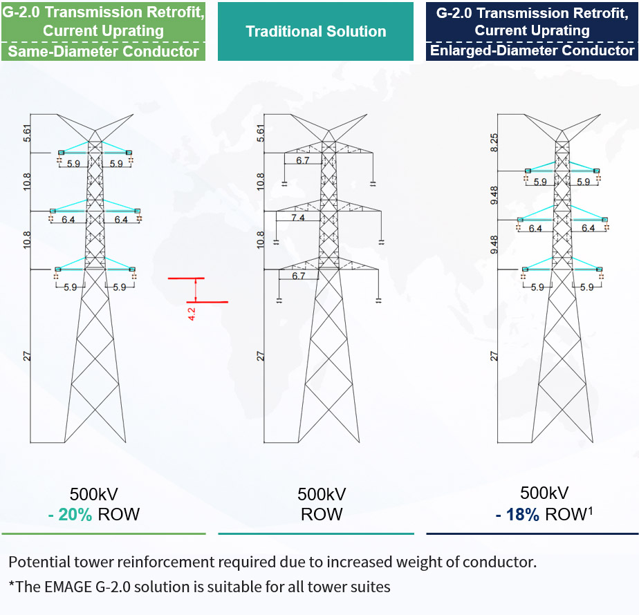
Compared to Traditional Solution
Using Same-diameter HTMS Conductor
Post-upgrade Capacity ≈ 1.7 ~ 1.9× Pre-upgrade capacity
Enlarged-diameter Conductor
Post-upgrade Capacity ≈ 2.1 ~ 2.2× Pre-upgrade capacity
Overall Advantages
- Project schedule greatly shortened
- Unit capacity cost significantly reduced
- Much less land use
- Significantly improved reliability
- Significantly lower carbon footprint
- Easier Social Permitting
Brownfield Solution - Voltage Uprating
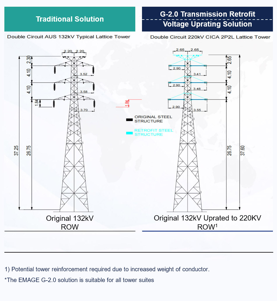
Compared to Traditional Solution
Voltage Uprating
Post-upgrade Capacity = 2.5 ~ 3.3× Pre-upgrade capacity
Feasibility of Voltage Uprating
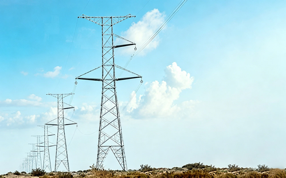
Traditional tower electrical restriction: Phase to ground clearance
EMAGE solution electrical restriction: Phase to phase clearance (CICA replacing of line insulator and steel cross-arm)
Overall Advantages
- Project schedule significantly shortened
- Unit capacity cost significantly reduced
- Much lower land take
- Reliability greatly improved
- Carbon footprint significantly reduced
- Easier Social Permitting
Real validation does not happen in the lab. It happens on the grid.
We have built a global application evidence chain — every project paired with quantified benefit, in-service duration, and client confirmation. From polar cold and tropical marine to high altitude and heavy pollution zones, the performance of our solution families across climate bands and voltage levels is documented.